If you ask people what the first Atari ST-family clones were, most will answer with names like Hades (1996, 68040) and Milan (1998, 68040). Very few will mention the Medusa T40 (1994, 68040, although one could argue that this is not a clone, but just a very invasive accelerator) or the spectacularly rare GE-Soft Eagle (1994, 68030). Regular readers of this blog will of course know the 1988 IBP 190ST as the first Atari ST clone (which aimed at bringing the ST architecture to the industrial world).
Therefore, I was very excited when I was offered a 19″ Atari ST computer at the VCFB 2022 that I did not know anything about. I received it recently and it turns out to be a previously unknown Atari ST clone, possibly even the only one existing today.
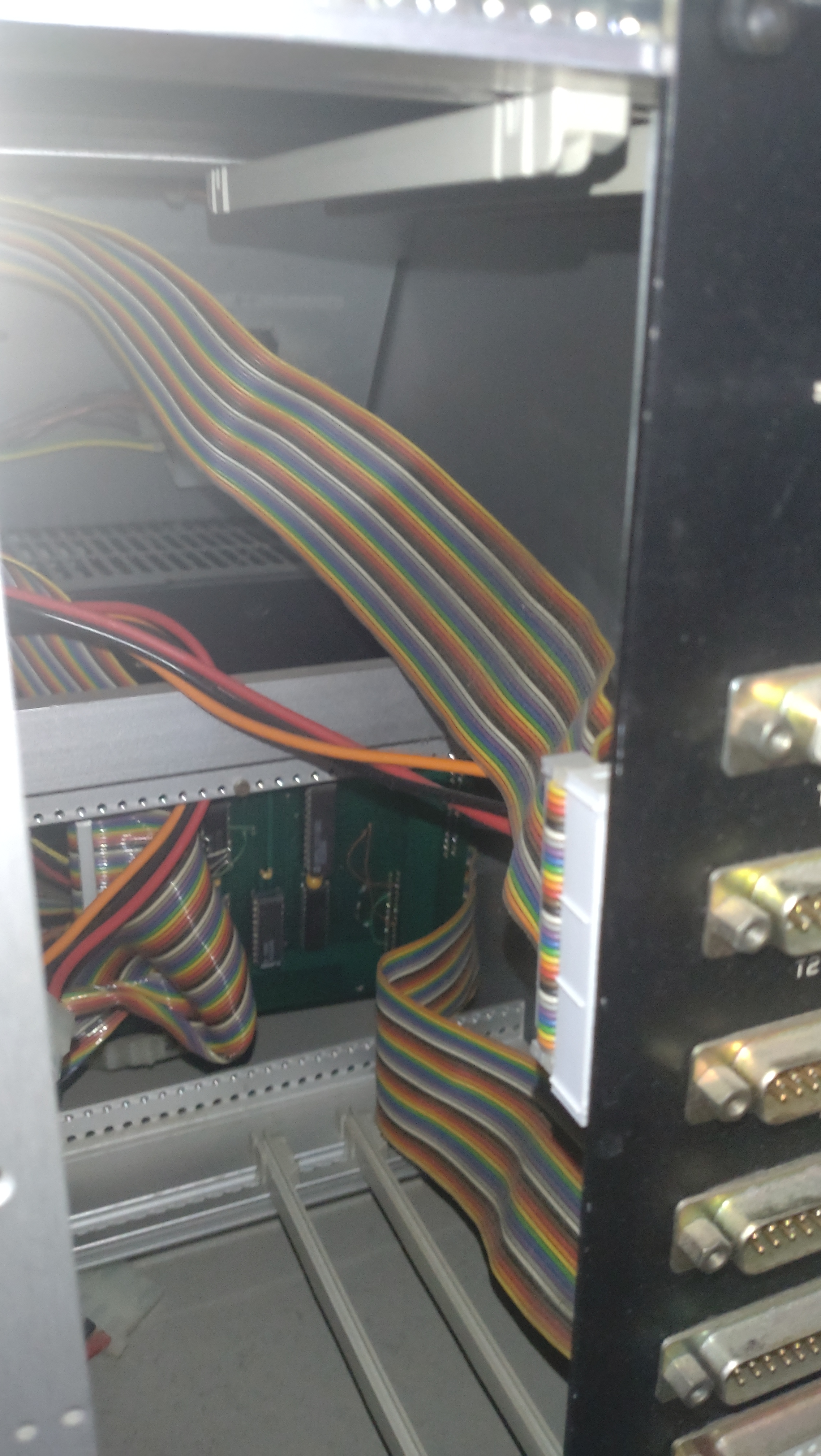
“Previously unknown” unfortunately also means that there is very little information available and we have to speculate more than usual to fill in the gaps. In such cases, the best approach is to examine the corpse the computer first and then start from there. The computer came in a (not so handy) 19″ rack, clocking in at a total over 30 kg. Here it is:
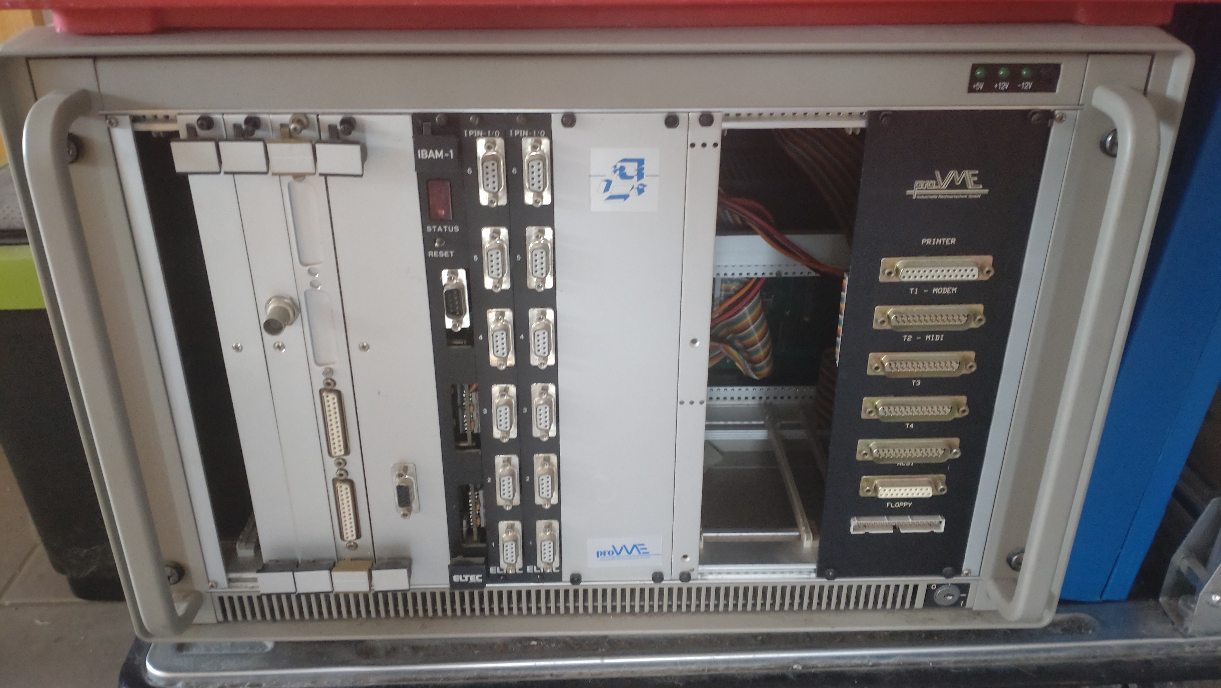
The ST would have been the first module on the left (it is out in this picture), then some other, 3rd party modules, a little bit wider panel with nothing behind in the middle, an FDD-and-HDD module to its right (also missing), and then a black panel with a number of interfaces on the right. Two of these interfaces say “Midi” and “ACSI”, but these are the only hints to a possible ST inside. Now, the rack also came with two peripherals which scream “Atari ST”: an SM124 monitor and a ST-style keyboard which connect to the (non-ST-standard) interfaces on the ST module.
The modules of the rack which are interesting to us bear a company name: “proVME”. This company (whose official name is “pro_VME”) played a small role for the Atari ST as it was the first company to introduce a really compatible accelerator for the Atari ST, the “Hypercache ST” from 1989. It consisted of a replacement PCB for the 8MHz Motorola 68000 CPU of the ST. This PCB hosted a 16MHz version of the same CPU and an 8kB instruction cache and a 8kB data cache in order to cope with the rest of the 8Mhz Atari. They followed this model up with the Hypercache ST+ which used two IDT7174 chips as the cache (interestingly, this and the following accelerator, the hyperCache 030, are later on sold and further developed by the same company GE-Soft that creates the Eagle in 1993/1994…).
Ok, now it is time to take the ST module out of the rack and have a look at it.
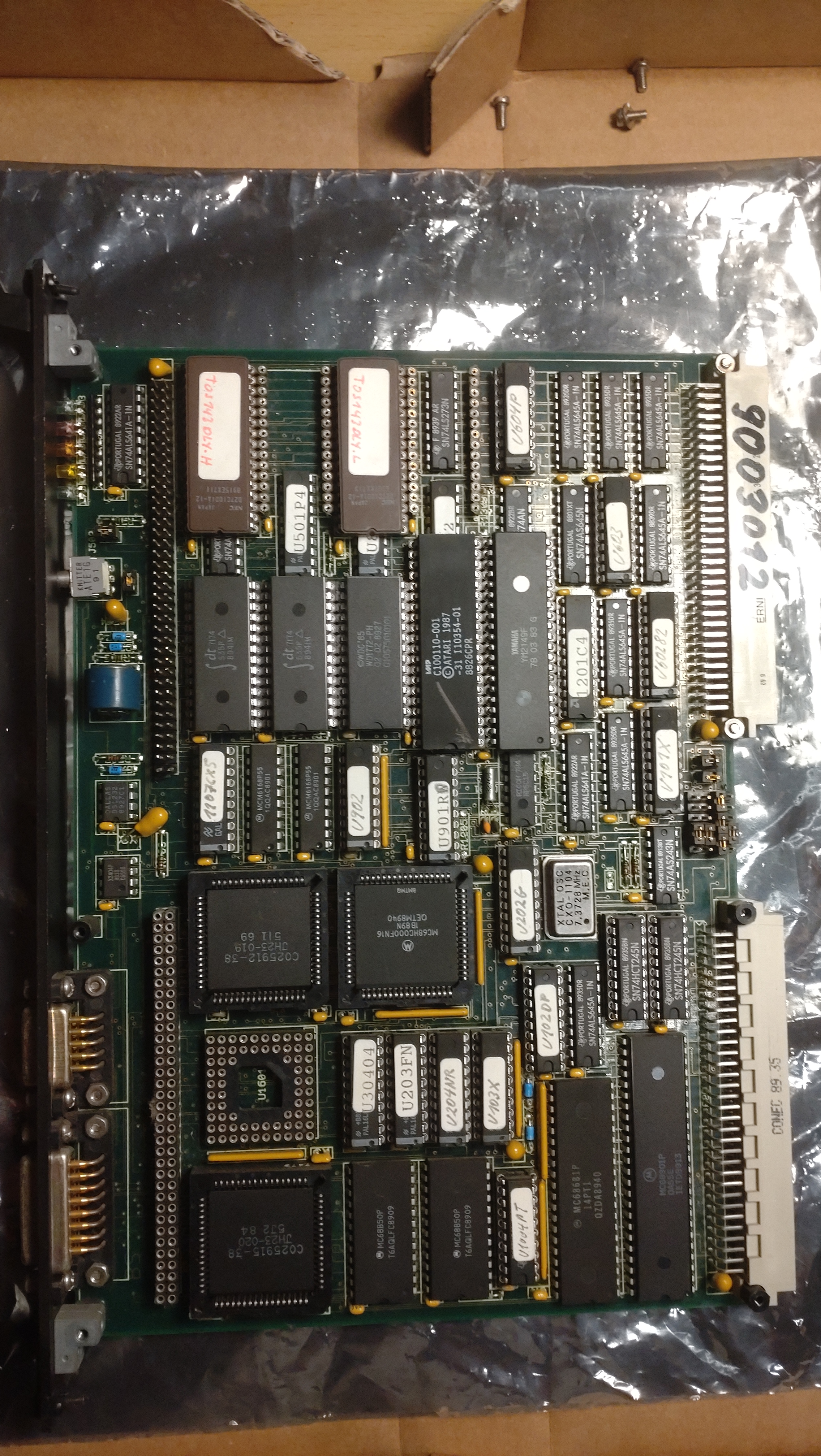
First, we can see the mainboard. There are a lot of chips we recognize from a Mega ST:
- 2 D27C1001A-12 EEPROMs with a label “TOS143DLY”
- 1 Yamaha YM2149F (sound chip)
- 1 C100110-001 Atari ASIC (DMA)
- 2 C025912-38 (MMU)
- 1 MC68901P (MFP)
- 2 MC68B50P (ACIA)
- 1 empty socket (for an 68881 FPU?)
The CPU is a MC68HC000FN16 (which actually runs at 16 MHz). Apart from the faster CPU, the only special thing is that there are two MMU chips, and it is unclear to me why. Also the TT has two MMUs (one for the ST RAM and one for the TT RAM), but I doubt that we have two types of RAM here, too.
The EEPROMS probably contain a modified version of TOS 1.043, but I did not check that. There are two more empty ROM sockets.
And then there are some chips we would normally not expect in an ST:
- 2 IDT 7174 8kx8 SRAM&Address Comparator
- 1 MC68681P (DUART)
The IDT chips are the same as in the Hypercache ST+ accelerator, so in conjunction with the faster CPU it seems as if the accelerator is here already integrated into the architecture. Sweet!
We are also missing some chips:
- the entire RAM
- the Shifter
- the GLUE
Additionally, we have four connectors on the board:
- 2 x DIN 41612, type C, 96-pin (one VME interface and one proprietary interface)
- a 74-pin bus on the top
- a 70-pin bus on the bottom
The rest of the space is filled with discrete logic, GALs, PALs, and smaller chips.
There is a 2.4V NiCd battery with 30 mAh (which we removed briefly after this picture was taken because it already started to leak).
We will find the RAM and the Shifter on the daughterboard, but the GLUE is nowhere to be seen.
My hypothesis is that they could not use the GLUE chip because of the differences of this computer to a standard Mega ST and because the VMEbus has some needs, too. If this is true, probably the colorful selection of PALs, GALs, and discrete logic contains the needed logic that is normally packaged in the GLUE chip.
Finally, at the front, there is a 9-pin sub-d keyboard and a 15-pin sub-d display interface as well as a 2-direction switch labeled Reset on the top and xxxx on the bottom.
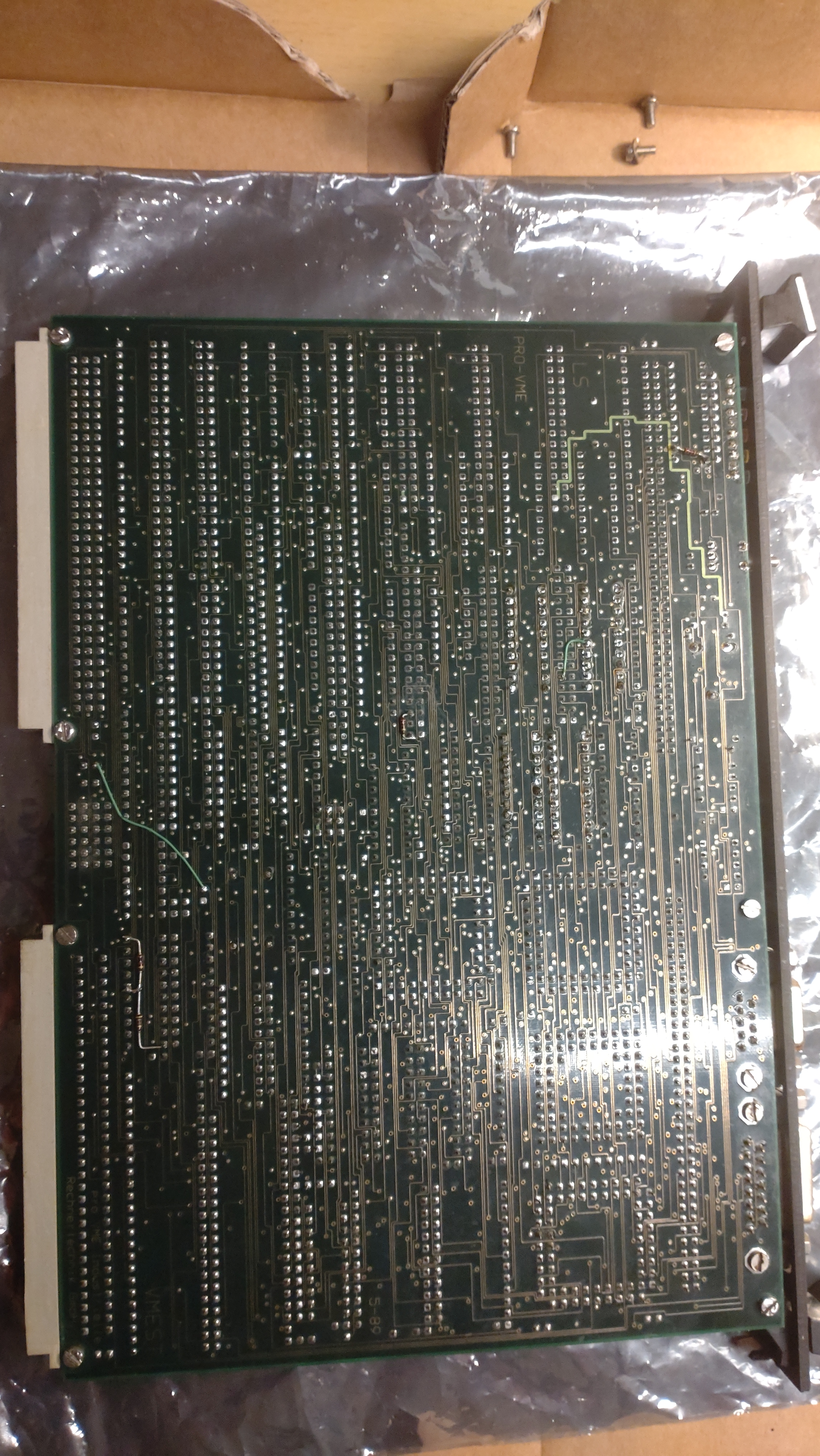
The back of the PCB is empty with 5 locations having patches:
Oh, and yes, finally: the name of the model can be found on the back of the mainboard as well:
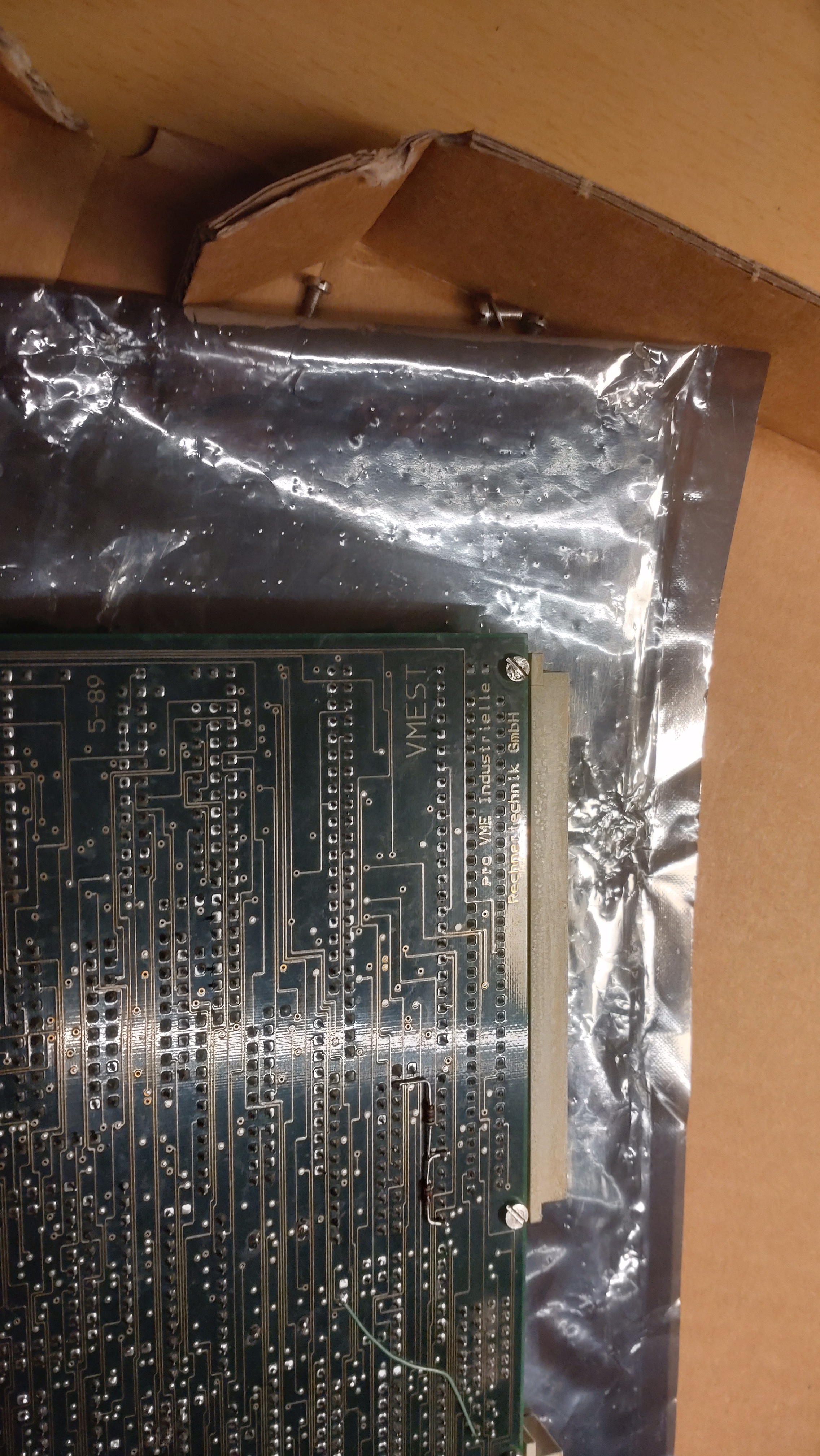
It’s the VMEST (this names makes a lot of sense, because it is an ST for a VMEbus system).
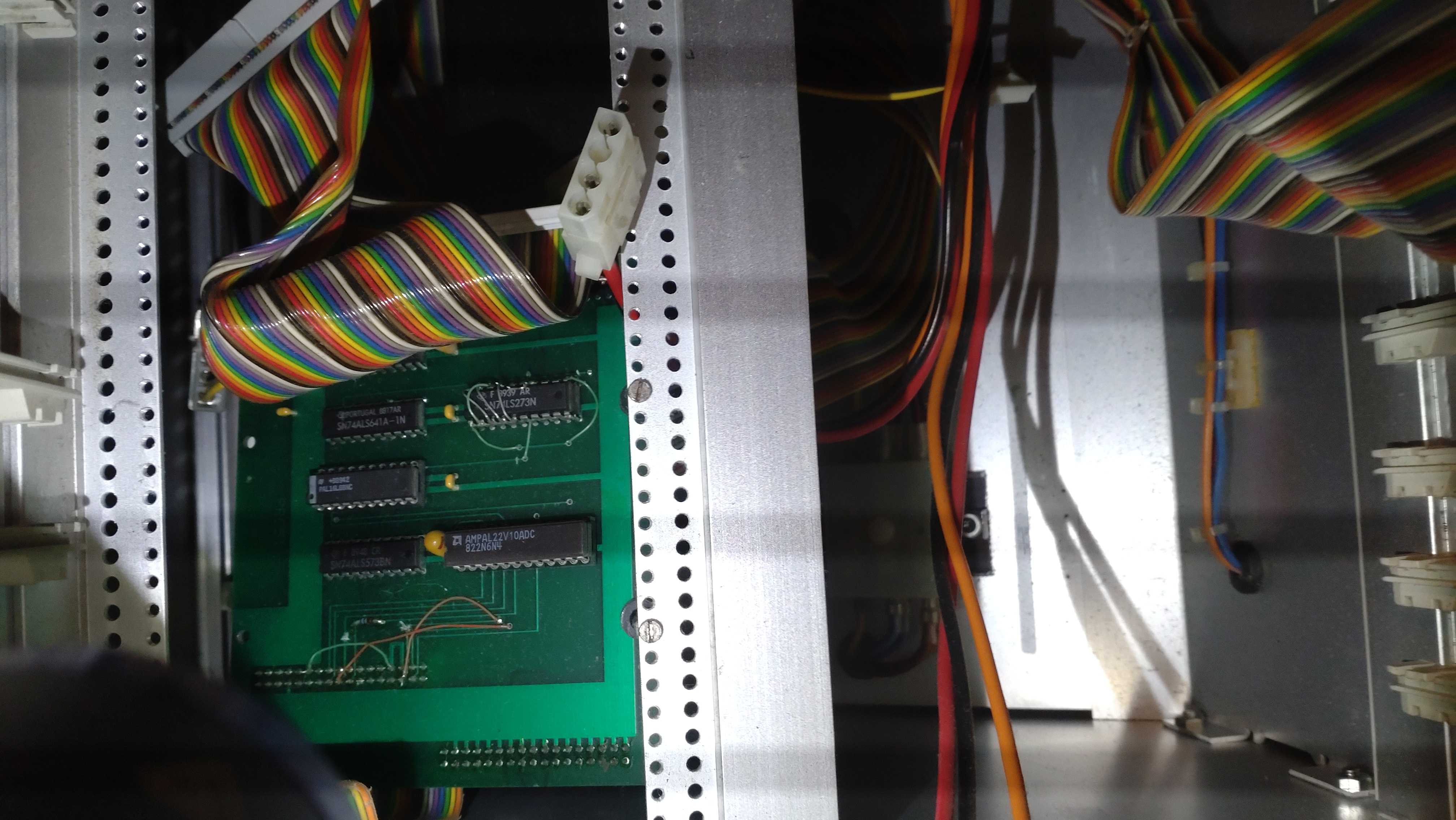
On the top of the mainboard, there is a daughterboard:
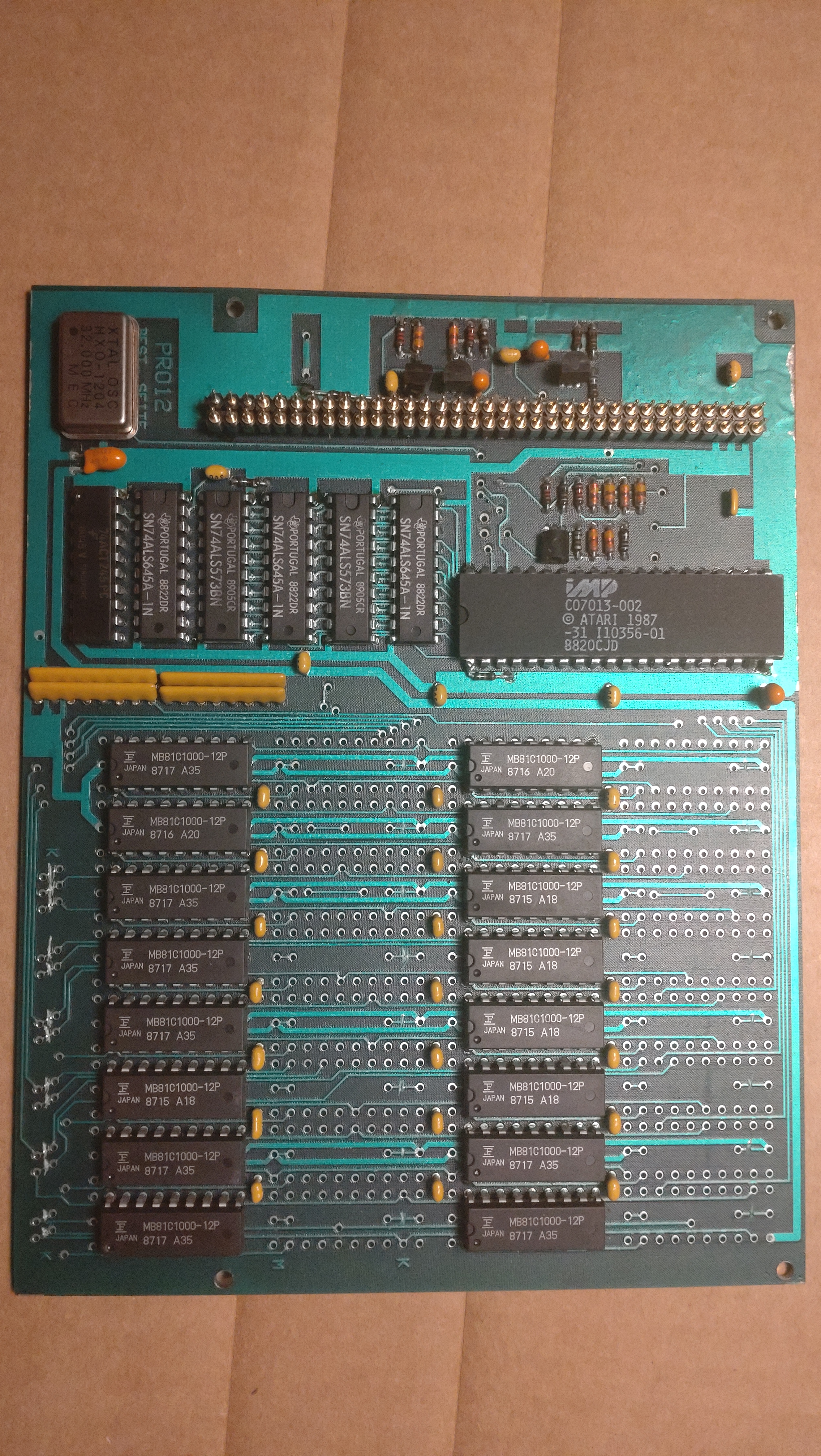
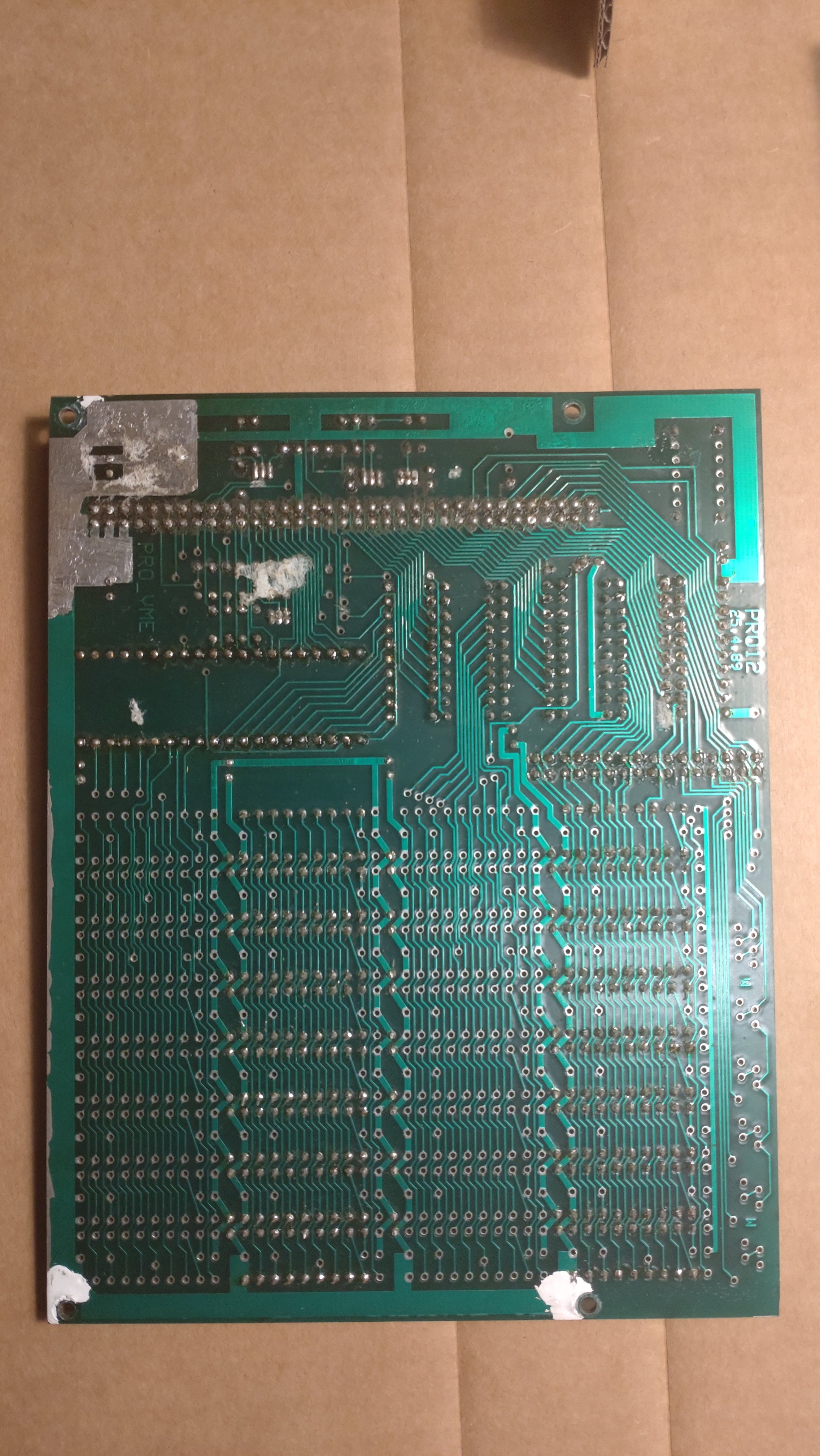
The PCB says PRO12, it is unclear to me what this means. The board contains four rows of chip space for 8 1Mbit chips, i.e. a maximum of 4 MB of RAM which fits perfectly to the ST architecture. As you can see, only two rows are populated, so this board has 2 MB of RAM. As I said before we can also find the Shifter chip on the daughterboard, as well as a 32 MHz clock chip. The daughterboard also contains a row of connector pins. The bottom of the daughterboard is boring:
We will now have a look at the other elements of the rack that belong to the VMEST.
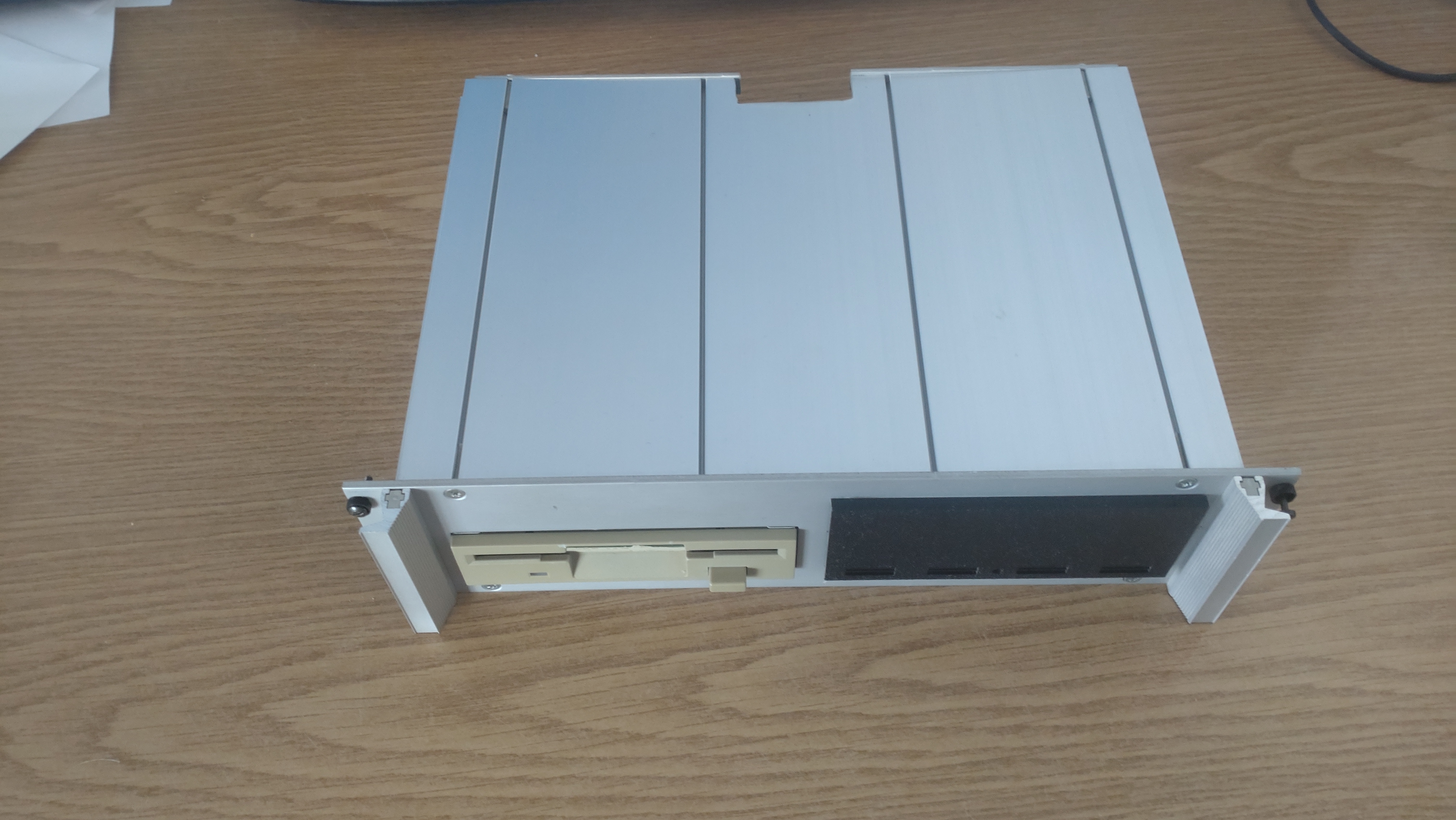
HDD-AND-FD-module
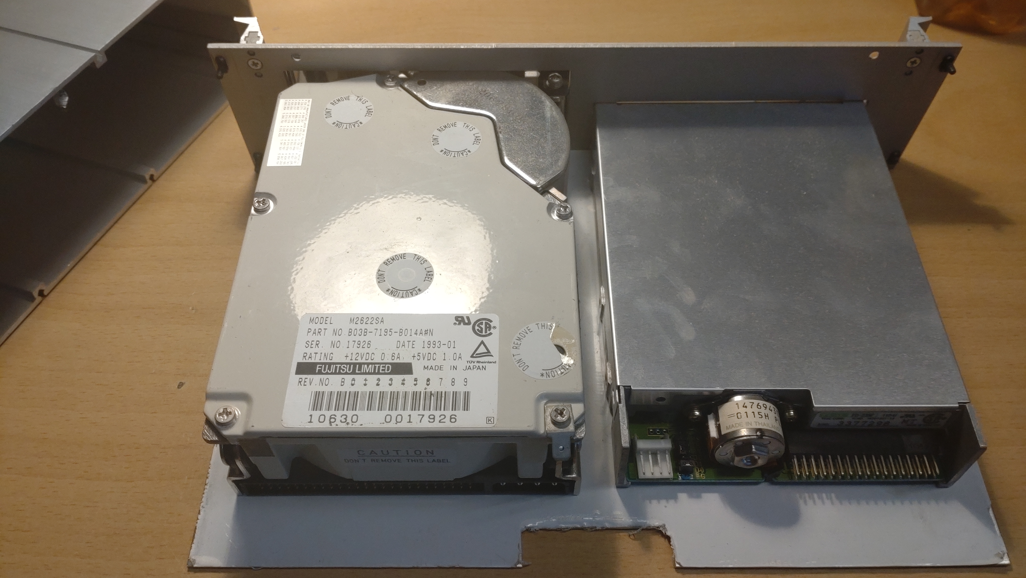
This is simply a 19″ module that contains a double-sided, double density floppy disk drive and a SCSI harddisk drive:
The HDD is a Fujitsu M2622SA 330MB SCSI-2 drive and the FDD is a TEAC FD-235F 112-U.
Breakout Panel and ACSI-SCSI Converter
The VMEST mainboard has a second 96-pin connector (the one on the bottom). This connector basically provides signals of all of the peripherals that can be connected to a Mega ST. You can see the backplane side of the connector here:
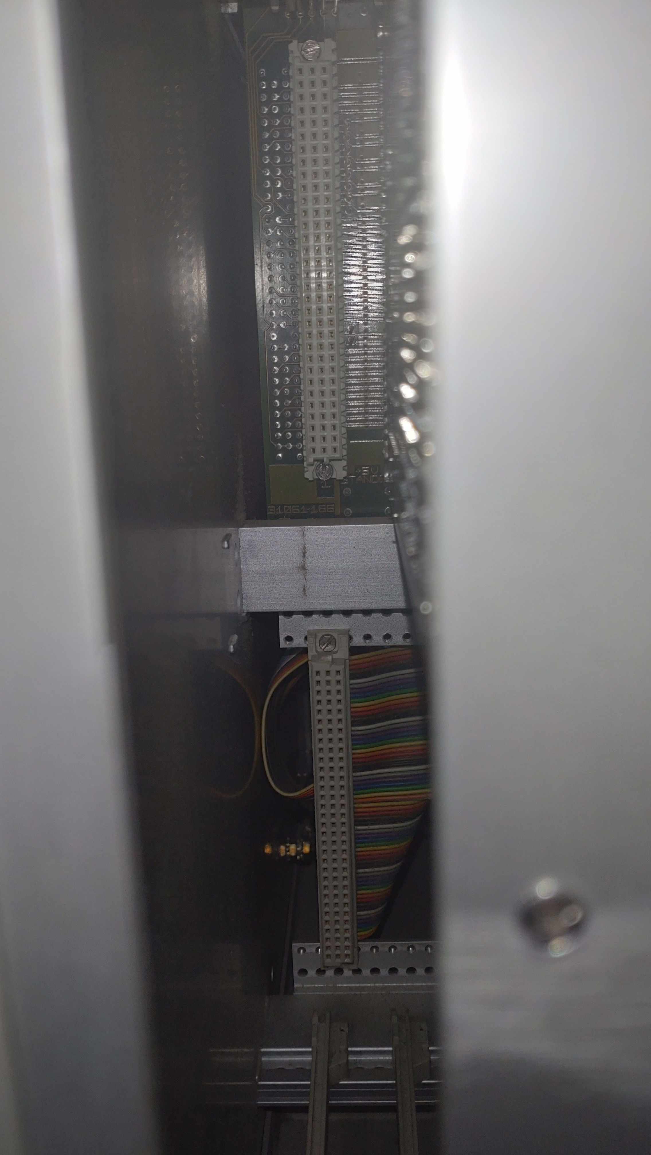
The cable of this connector ends up in three cables. One of these cables leads the breakout panel, the other one to a PCB which more or less dangles in the back of the rack:
The breakout panel is also a PCB that looks like this:
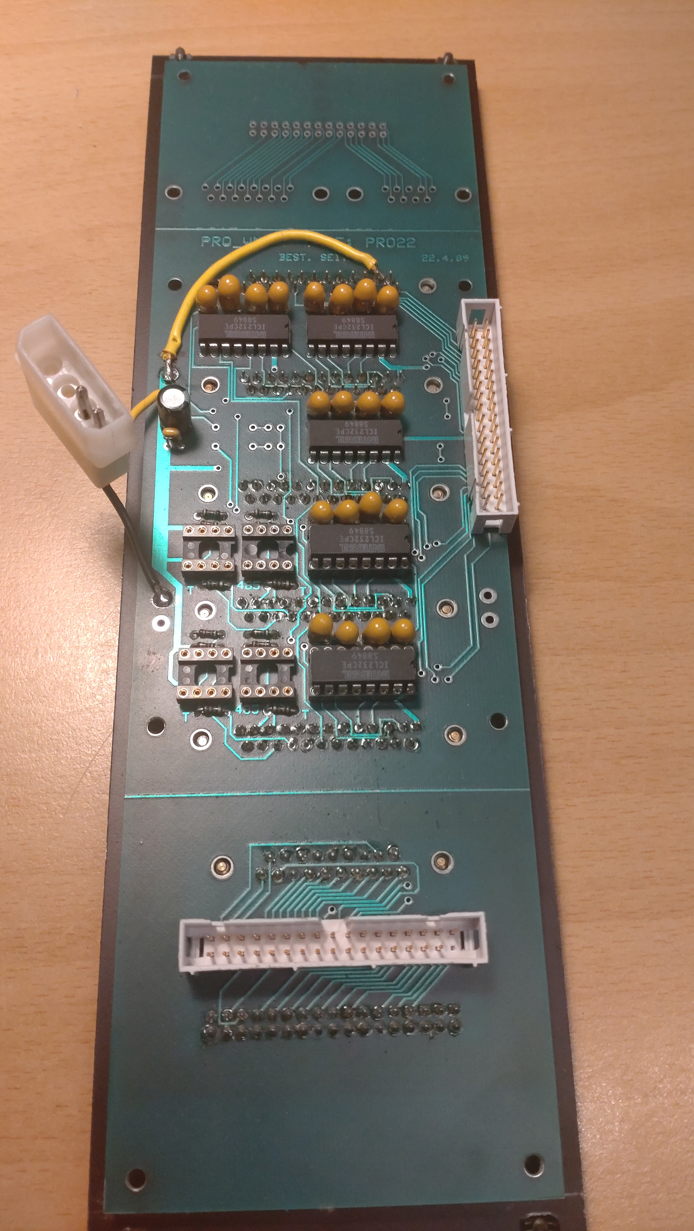
This is the front of the panel:
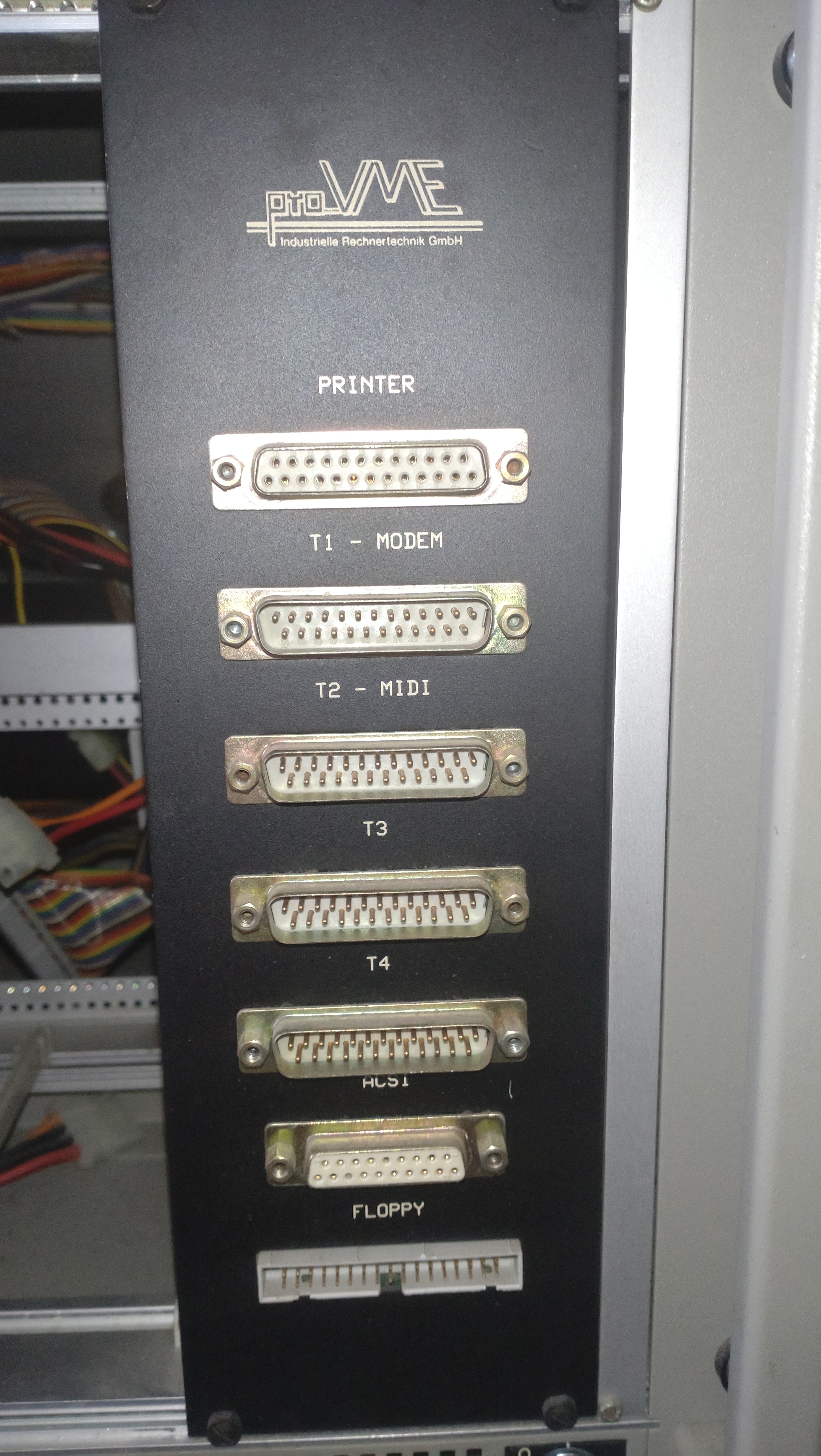
This panel contains mainly 25-pin d-sub interfaces for a printer, a modem, MIDI, probably two more serial interfaces (named T3 and T4), ACSI, and a floppy interface. The MIDI interface is also a 25-pin d-sub plug, the other interfaces are the same interfaces as on a Mega ST.
Let’s talk about the mysterious PCB inside the rack. It is connected to the second cable coming from the VMEST board. Here is a (bad) picture from it:
It is a pro_VME development (with another ProXX name on it) and it ends up in a cable leading to the (SCSI) HDD: it is an ACSI-SCSI converter.
The third cable from the VMEST mainboard finally is a floppy cable that can be connected either to the FDD or to the connector on the breakout panel.
Monitor and Keyboard
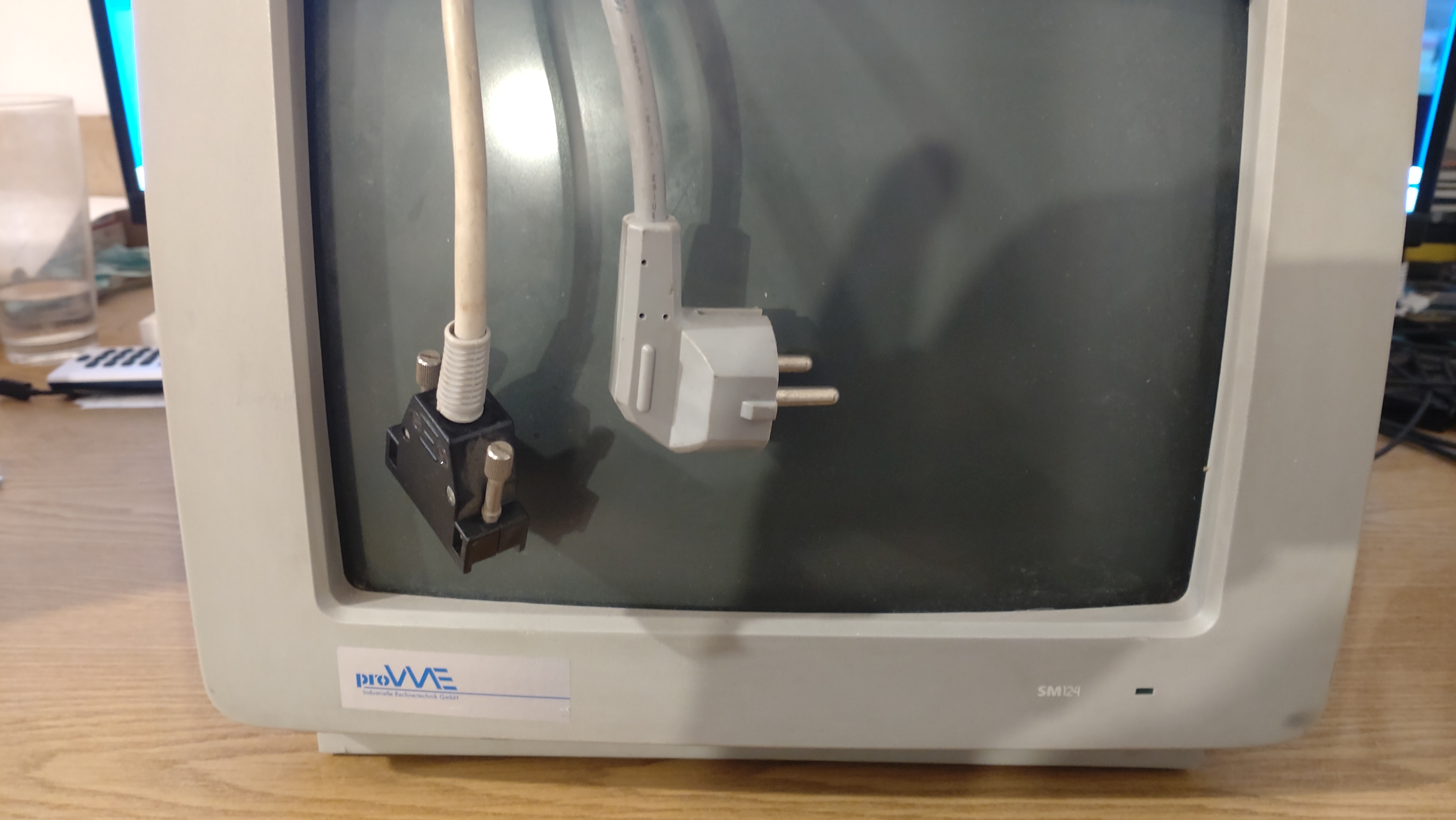
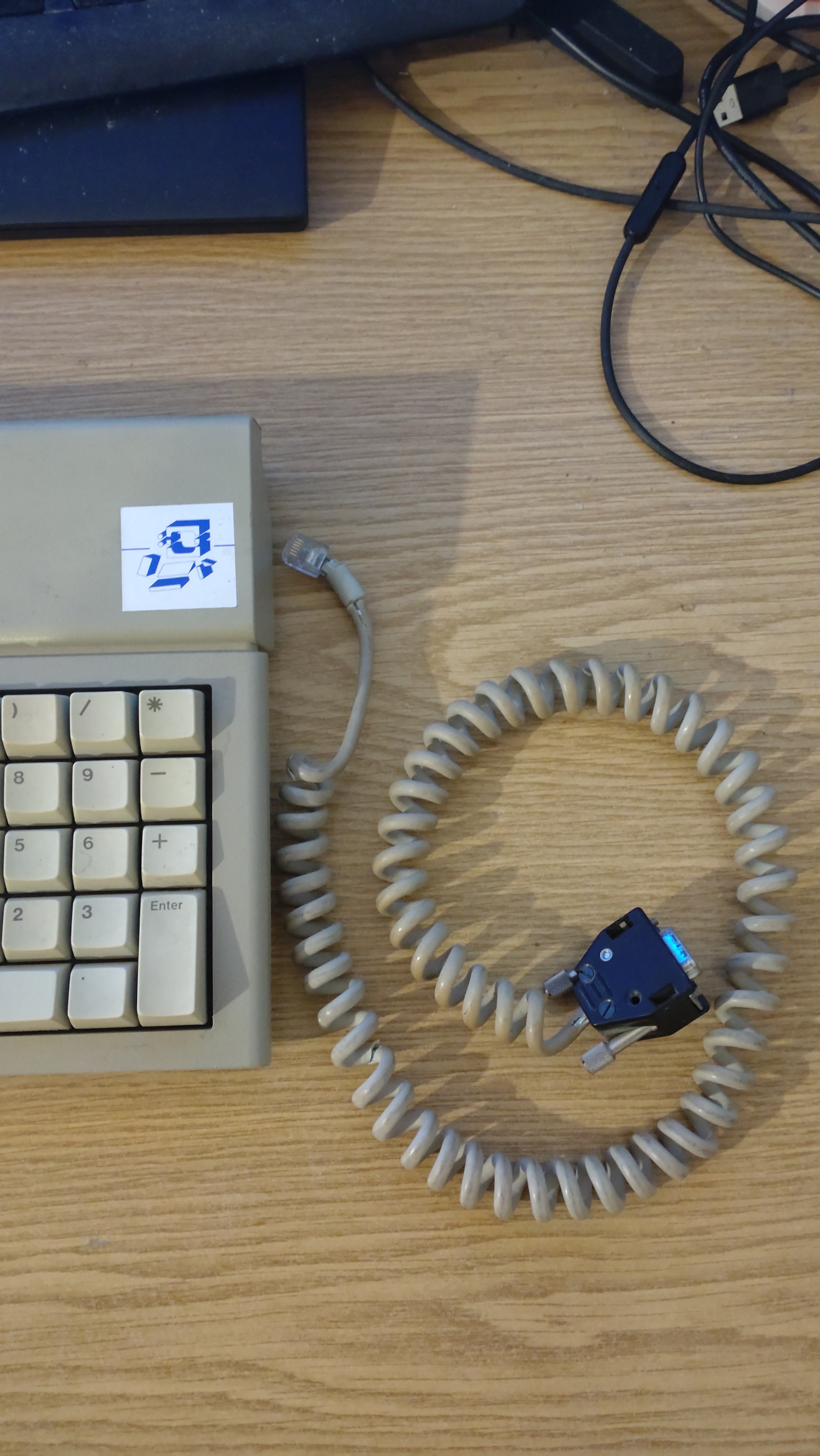
These are quite boring. Standard Mega ST keyboard with a standard cable that has one end with the proprietary VMEST connector. Standard SM124 display (newer version) with the proprietary VMEST connector on the display cable. I hope to report on the pin assignment soon, but then, also, who can use this information except me? Both keyboard and monitor boast a pro_VME sticke
The VMEST on the Internet
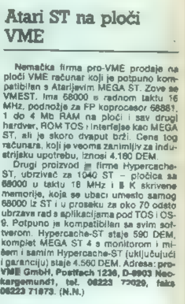
Finally, something that does not take long writing about it. There is one(!) mention of the VMEST that I could find. It is a short snippet from a Serbo-Croatian computer magazine from January 1990:
Also, there is an indirect mention of what could be a VMEST in the German “ST Computer” magazine (1993/10): “Normen had his first contacts to the company proVME at the Atari Fair 1989 that then showed the first modification of the ST to 16 MHz plus cache in form of a VMEbus card which was meant as a low-cost graphics terminal for industrial applications.” (“Auf der ATARI-Messe 1989 knöpfte Normen dann die ersten Kontakte zur Firma proVME, die damals den ersten Umbau des ST auf 16 MHz mit Cache gezeigt haben, und zwar als VME-Bus-Board, gedacht vor allem als preiswertes Grafikterminal für Industrieanwendungen.”) Finally, there is another mention in a German Atari ST magazine from 1989, but it gives no details and list “Becker Ing.-Büro” as the distributor, which is possible, but also not that likely.
Why aren’t there more VMESTs out there?
Difficult. I have the feeling that the VMEST is a (hopefully working) prototype and that the machine was never really sold. Maybe the VMEbus version of the IBP 190ST was available earlier or did cost less. If you happen to also own a VMEST, I would certainly like to hear from you!
Conclusion
There you have it: The VMEST from pro_VME is an industrial clone of the Mega ST for VME racks. It consists of three pieces: The motherboard that also includes a 16MHz accelerator and offers sockets for up to 4MB of RAM, an ACSI-SCSI converter and a breakout box for more interfaces. This is the only machine of this type I have ever heard of and the information on the Internet about it are virtually non-existent. It might be a prototype and probably never hit the market.
From a collector’s point of view…
the VMEST is a dream. Probably the only one in the world. Take that, mass-market IBP 190ST with your sales in the dozens 🙂
Technical Data
Manufacturer: pro_VME
Model: VMEST
CPU: Motorola 68000@16MHz
RAM: 2 MB
ROM: 256 kB
The rest of the data is the same as an Atari Mega ST.
Initial Price: 4160 DM
Introduced in: 1989
Produced devices: unknown

Leave a comment